Ask ten suppliers what size truck scale you need and most will answer with a tonnage. Tonnage matters, but it is the second question. The first is whether the platform is long enough to capture the whole vehicle in a single weighing. This note explains how to work from the vehicles you actually run to a deck length, and where our standard, widened and modular platforms fit. We keep to figures we can put on a drawing; the issued specification, not the brochure, governs the final machine.
Start with the vehicle, not the catalogue
Gross vehicle weight sets the capacity class, but wheelbase and axle spread set the length. Begin by listing the longest vehicle that will use the scale: a rigid tipper, a tractor with a semi-trailer, or a longer combination if the site handles them. Measure from the centre of the front axle to the centre of the rearmost axle, then add the tyre contact patches and a margin for the driver to stop squarely. That number, not a round figure copied from a competitor's brochure, is the target deck length.
A common mistake is to size for the average truck. Fleets are mixed. The scale has to serve the longest combination on the busiest day, including the occasional hired vehicle that is longer than anything you own. If one axle group remains on the approach ramp during a static weigh, the reading is a partial weight, and no indicator can correct for it afterwards. The error is repeatable, which makes it easy to miss during a quick acceptance test and expensive to discover months later during a stock reconciliation.
Write the vehicle list into the enquiry. Distributors who send us the axle configuration and the longest wheelbase get a deck recommendation they can defend to their own client, rather than a guess that becomes a dispute at commissioning. A ten-minute measurement at the start of a project removes a class of problem that no amount of indicator tuning can fix at the end of it.
Why whole-vehicle weighing drives the dimension
A static weighbridge measures the reaction at the load cells while the vehicle is fully on the deck and at rest. If part of the vehicle is still supported by the approach, some of its weight goes into the ground instead of the cells. The result is a repeatable but wrong number, which is more dangerous than an obviously unstable one because it looks plausible on the printout and in the software log.
This is why platform length and approach design belong in the same conversation as capacity. The deck must be long enough that the driver can stop with the whole vehicle inside the weigh area, with room at each end so the tyres are not sitting on the joint between deck and ramp. Straight, level approaches of at least a vehicle length help the driver settle without braking on the platform, which keeps the load cells out of the shear forces that braking creates.
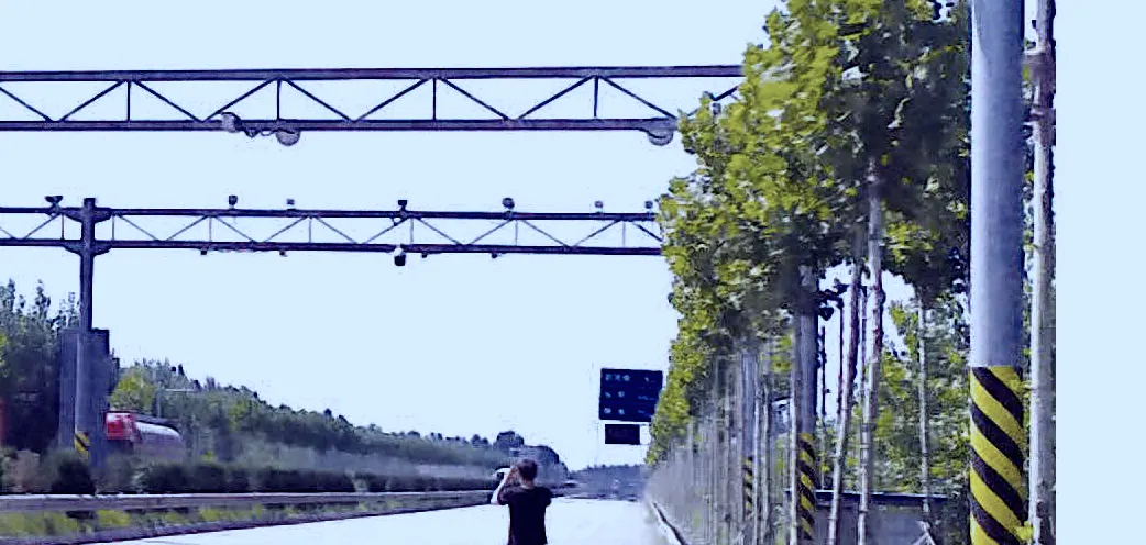
Weigh-in-motion changes the geometry. A 58 mm wide-flange plate sensor is buried directly without a civil pit and reads axles as they pass at 1-100 km/h, so a long vehicle is not a length problem in the same way. Full-wheel load integration cancels the error caused by eccentric or irregular driving rather than relying on a single stop position. But for a conventional static deck, axle spread remains the governing dimension, and that is the case this note is mainly about.
Standard, widened and modular platforms
Our standard deck measures 3,500 x 1,000 mm, with a widened version at 4,200 x 1,000 mm. Those are the nominal values from our standard build, and the issued drawing is the reference that governs orientation on site. The 4,200 mm option exists precisely for fleets whose wheelbases sit beyond the standard module, so it is a length answer to a vehicle question, not a premium trim level.
When a single platform cannot cover the longest combination, we build ZDG-type multi-platform assemblies. Two or more modules are joined so the combined deck matches mixed axle spacing, which is common at ports and logistics parks where rigid trucks and articulated combinations share one lane. Because each module is a fully welded U-section closed cavity, the assembly behaves as one stiff deck rather than a set of loosely connected plates, and the joint positions can be set to fall between axle groups rather than under them.
Capacity is chosen along the same axis but independently. Our truck weighing scale lines cover the 20, 50 and 100 ton classes, and the capacity hub lets you compare them side by side. A longer deck usually goes with a heavier class, but length follows wheelbase while capacity follows the heaviest gross vehicle weight. Treat them as two lines on the specification sheet, not one decision.
| Input | What it fixes | Where to confirm |
|---|---|---|
| Longest wheelbase | Minimum platform length | Fleet vehicle list |
| Axle group spread | Module joints and count | Axle configuration drawing |
| Heaviest gross weight | Capacity class (20/50/100 t) | Vehicle rating plate |
| Static or in-motion | Deck or plate sensor | Operating requirement |
| Standard deck | 3,500 x 1,000 mm nominal | Specification sheet |
| Widened deck | 4,200 x 1,000 mm nominal | Specification sheet |
| Modular build | ZDG-type multi-platform | Issued drawing |
FIG. 02 — Plan view, deck length set by wheelbase, not to scale
An over-long deck costs more steel, a longer foundation and more approach work without improving accuracy. Size to the longest vehicle plus a sensible stopping margin, not to the largest number in the catalogue.
Pit, pitless and the foundation behind the length
Once length is fixed, decide how the deck sits. A conventional pit-mounted scale needs a reinforced concrete pit with drainage and a sump; the deck finishes flush with the road. A pitless or above-ground arrangement uses shallow ramps and keeps the structure clear of standing water, which simplifies maintenance on sites with a high water table. The choice affects the approach length as much as the pit depth, so it belongs in the sizing conversation rather than being left to the civil contractor.
For weigh-in-motion the geometry is different again: the 58 mm direct-bury plate needs no civil pit at all, is rated IP68 for the buried environment and carries 150% overload. It returns +/- 0.5% dynamic accuracy across the 1-100 km/h range, so axle spread is handled by the sensing method rather than by deck length. Whichever route you choose, foundation and approach length are part of the size decision. Our installation and service page sets out the civil scope that accompanies a deck, and the deck drawing and foundation drawing are issued together so the two do not drift apart.
A sizing checklist to send with your enquiry
A useful request is a short specification, not a single question. Put the following into it: the longest vehicle type and its wheelbase, the axle configuration and axle group spread, the heaviest gross vehicle weight, the mix of rigid and articulated vehicles, whether weighing is static or in-motion, the deck length you have in mind, pit or pitless preference, the site country and destination port, the preferred incoterm and the estimated quantity.
With those fields an engineer can return a documented specification rather than a catalogue number. Our commercial frame stays deliberately simple: lead time is around 60 days from a confirmed drawing, minimum order is 1 unit, payment is by T/T, and we quote EXW, FCA, FOB, CNF, CIF, DAP or DDP. Trusted in 70+ countries with an annual output of 10,000+ units, we still treat each deck as a drawing-first job. If you are unsure which way to go, the price guide explains how length, module count and foundation type move a quotation, and the construction detail shows what sits behind the dimensions.
When you are ready, send the wheelbase, axle spread and capacity to our engineering desk through the contact page. We return the recommended deck length, the module count, the construction and coating figures and a comparable quotation, so the size on the drawing matches the size that arrives on site.